
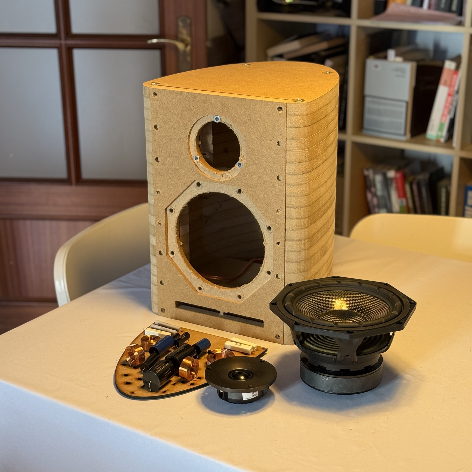
«Lira» geometry
A curved section with a flat baffle and an elliptical back. It removes parallel walls, spreads the internal resonant modes and breaks up standing waves.
Prototype in development
427 interestedA two-way loudspeaker built on one simple idea: put acoustic behaviour ahead of what mass production allows.
Drivers byBeymaKeep me posted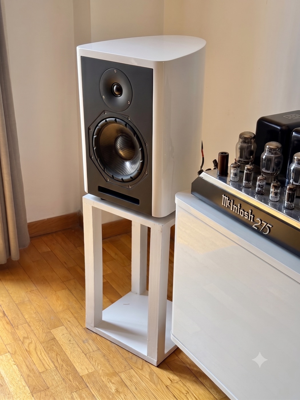
Inside the model
This is the actual CAD model the workshop DXFs come from: 120 parts, each with its place and its assembly order. Spin it, open it step by step and tap any part to see what it does and why it matters for the sound.
Project status
Deciding what the loudspeaker had to get right before drawing anything, choosing the drivers and taking the system into simulation.
The cabinet: curved geometry with no parallel walls, a 40 mm laminated body and every manufacturing drawing generated from a parametric 3D model.
Matching the crossover to the Beyma drivers to get everything out of them, settling the components and taking it from schematic to manufactured board.
Build, listen, write down everything that did not fit and draw it again. That is where the current design came from, now in high-precision machining.
The first measurements are done and published. What is missing is someone outside, with an anechoic chamber, confirming them.
Turning a prototype into something that can be manufactured, finished and sent to someone’s home without arriving damaged.
The project has been told in the open from day one. What is left is playing it in front of people and opening the first series.
The method
Loudspeaker design stopped depending on mysticism and intuition decades ago. Today there are simulation tools, analysis systems and a large body of literature that let you predict precisely how each decision affects the final result. The Opus I applies that accumulated knowledge.
Development focused on two critical goals:
That does not mean there is one correct sound: certain physical behaviours are statistically preferred because they cause less listening fatigue and stay closer to the original message.
The kit format as a philosophy. Many of the mechanical solutions in the Opus I would be unworkable on an automated assembly line, because of machining cost and curing time. The kit brings back the audio culture of the sixties and seventies: building it is not only cheaper, it is how you get to understand the loudspeaker from the inside. It is also, to date, the first commercial loudspeaker kit designed and manufactured in Spain with Beyma drivers, which are Spanish-made too.
The project is still being fine-tuned. Before the design is closed, the system will be checked with near-field and far-field measurements and with blind comparative listening against reference monitors on the market, keeping the result clear of price or expectation bias.
Construction
Every geometric and material decision balances acoustic performance against what can realistically be assembled at home. The design is meant to make the result depend on the project, not on the previous skill of whoever builds it.
A curved section with a flat baffle and an elliptical back. It removes parallel walls, spreads the internal resonant modes and breaks up standing waves.
A structure made of 23 CNC-machined board slices. The many glue lines between layers act as structural damping and reduce the energy radiated by the panels.
Four M8 steel threaded rods run through the body from top to bottom and keep it under constant pressure. They raise mechanical stiffness and guarantee a perfect seal, with no butt joints.
The tuning duct is milled straight into the wooden slices themselves. It avoids the tube resonances of commercial plastic ports and keeps the tuning dimensionally exact.
An 8NMFW woofer (carbon cone) and a T25M dome tweeter. Professional-grade components, chosen for their low dynamic compression and thermal stability at high sound pressure.
Both drivers sit flush with the baffle in micrometric rebates. This minimises edge diffraction at the front.
Every wooden part arrives numbered and tongue-and-grooved so it fits in one position only. No special tools and no hand-fitting required.
A passive crossover with air-core coils (no core to saturate) and polypropylene capacitors from Jantzen Audio and Dayton Audio. It includes impedance-correction and attenuation networks calculated for a clean transition between ways.
A custom rear terminal plate, laser-cut in black acrylic (engraved, with holes for the binding posts), integrated into the elliptical curve of the cabinet.
Foundations
The Opus I is not based on esoterics; it rests on technical literature verified in primary sources (AES, JAES, BBC Research). The core references for the design are:
The brands mentioned belong to their owners and appear only as a technical reference.
Crossover
The crossover is the brain of the loudspeaker: it splits the signal coming from the amplifier between woofer and tweeter, sending each driver only the band it can reproduce and protecting it from the one that would damage it. But it does more than «cut»: it corrects the frequency response, matches the levels of the two drivers, compensates their impedances and aligns their phase so both sound like a single coherent source. That is why a well-designed crossover is the difference between a loudspeaker that measures well and one that also sounds natural. And the maths is not enough without good materials: air-core coils (no core to saturate), low-loss polypropylene capacitors and non-inductive power resistors keep the signal clean, stable at high volume and faithful over time. In the Opus I the crossover is passive, built from Jantzen Audio and Dayton Audio parts, measured piece by piece and mounted on a printed circuit board shaped like the cabinet itself.
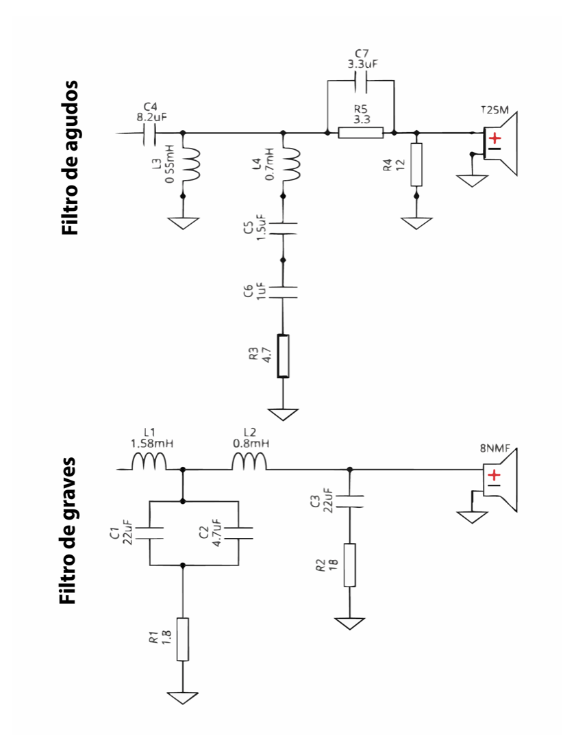
The two series coils (L1 1.58 mH and L2 0.8 mH) let the bass through to the 8NMFW and progressively hold back the treble. Capacitors C1 (22 µF) and C2 (4.7 µF) shunt what is left over to ground, and R1 (1.8 Ω) damps that network so the cut is clean and free of resonances.
C3 (22 µF) in series with R2 (18 Ω) forms a Zobel network at the woofer input. It corrects the impedance rise caused by voice-coil inductance, so the low-pass filter «sees» a stable, resistive load and works exactly as calculated.
C4 (8.2 µF) in series with L3 (0.55 mH) to ground forms a 2nd-order high-pass (12 dB/oct). It blocks the bass that would damage the T25M and passes only the top band it can reproduce.
L4 (0.7 mH) with C5 (1.5 µF) and C6 (1 µF) forms a series resonant network to ground that «sucks out» a specific peak in the tweeter response. R3 (4.7 Ω) sets the depth and Q of that trap, smoothing the curve without overdoing it.
R5 (3.3 Ω) in series and R4 (12 Ω) in parallel form an L-pad: they bring the tweeter level down to match the woofer sensitivity while keeping the impedance seen by the crossover constant. C7 (3.3 µF) bypasses R5 at the top end so the last octave keeps its air and sparkle.
Components

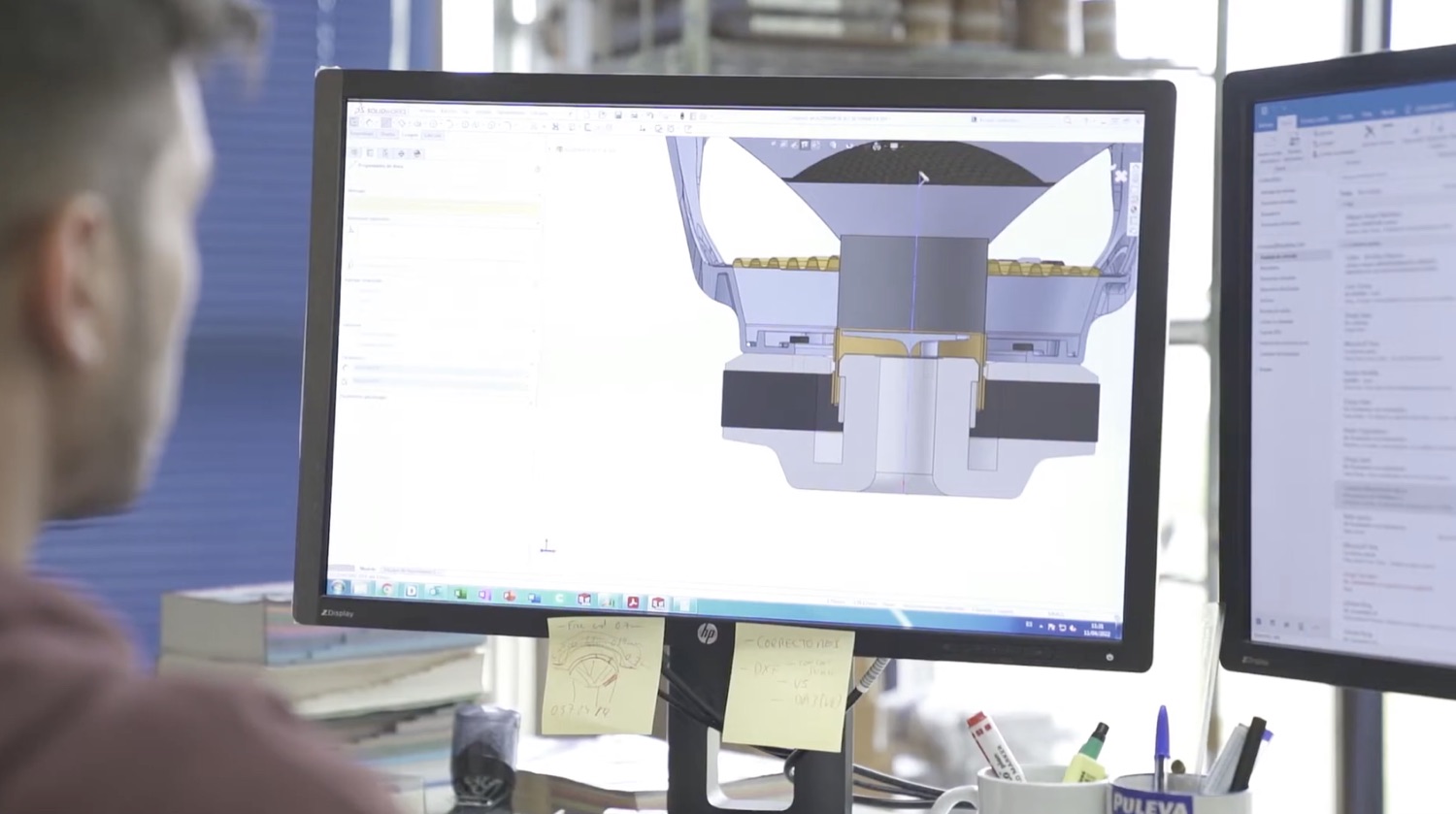
Both drivers in the Opus I come from Beyma’s NMF (Near & Mid Field) series: a new high-end range the Valencian manufacturer designed specifically for near and mid field —domestic high fidelity and recording studios. Developed over two years of multiphysics simulation in search of extreme linearity and minimal distortion, Beyma sums it up as «live sound at home».
Choosing the drivers is the decision that shapes a two-way design most: they are what moves the air. After comparing several brands, the drivers in the Opus I are Beyma, and not for a single reason.
Professional-grade components, not consumer catalogue parts. The NMF series comes out of two years of multiphysics simulation chasing linearity and minimal distortion: an honest base to build a good loudspeaker on.
Founded in 1969, Beyma is today one of the reference brands in professional audio in Europe. Behind every driver there are fifty years of accumulated craft.
Born for professional sound —tours, venues, studios— they take far more than you will ever ask of them at home. That ruggedness turns into peace of mind: a loudspeaker for years.
They design and manufacture in Moncada, Valencia. Working with a local manufacturer shortens distances and lead times, and keeps the project close to home.
In every contact, from engineering to sales, the same seriousness and the same good treatment. It is a pleasure to work with people like that.
But if I have to keep one reason above all the rest, it is the most human one: with Beyma you can talk. You pick up the phone and on the other end there are engineers, designers and a sales and communication team willing to discuss, to explain what you ask and to listen to what you propose. It is not a closed catalogue or a form that never gets answered. We are all people —and in the end, this is made by people for people.
Josep Maria Marimon
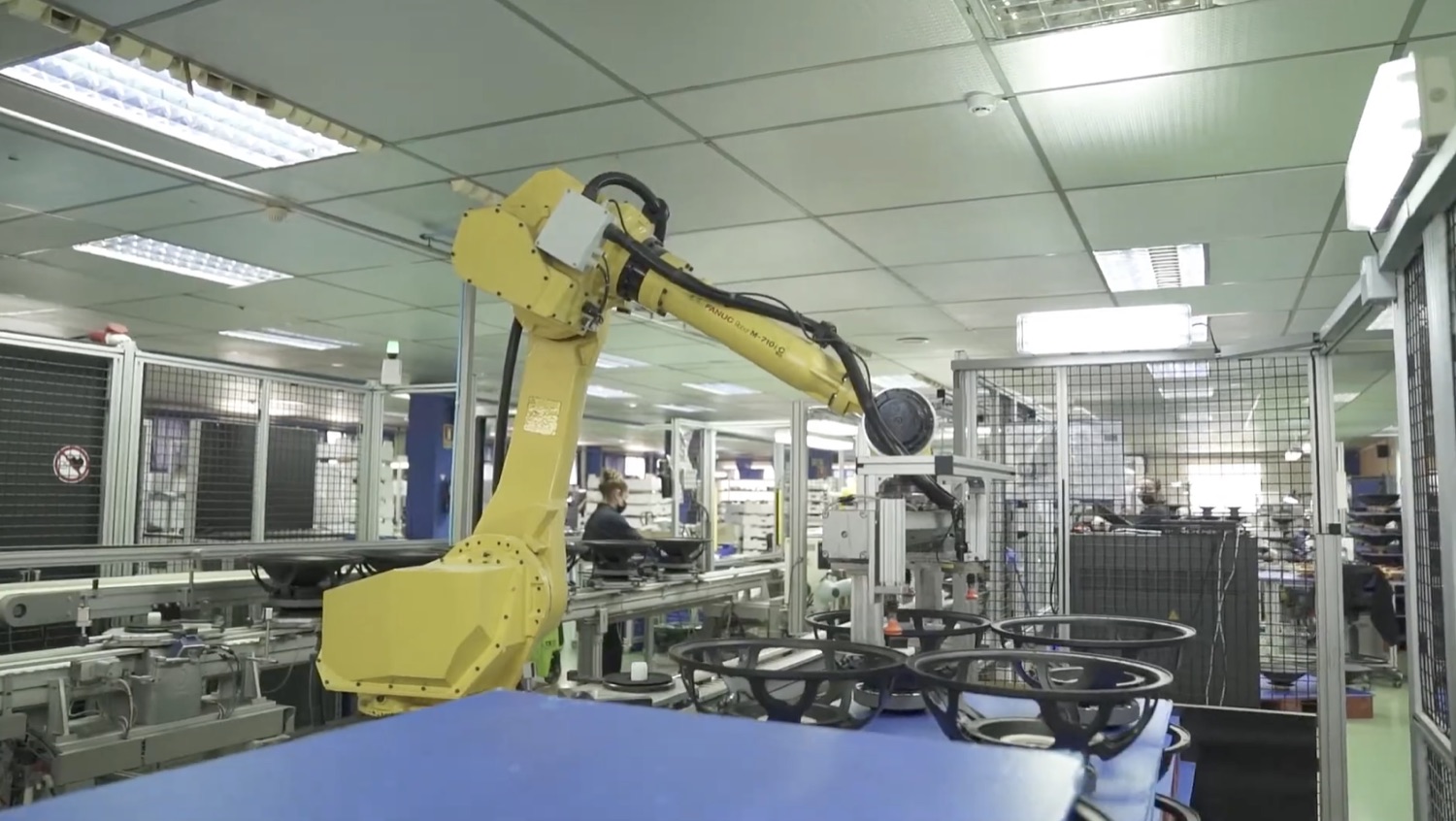
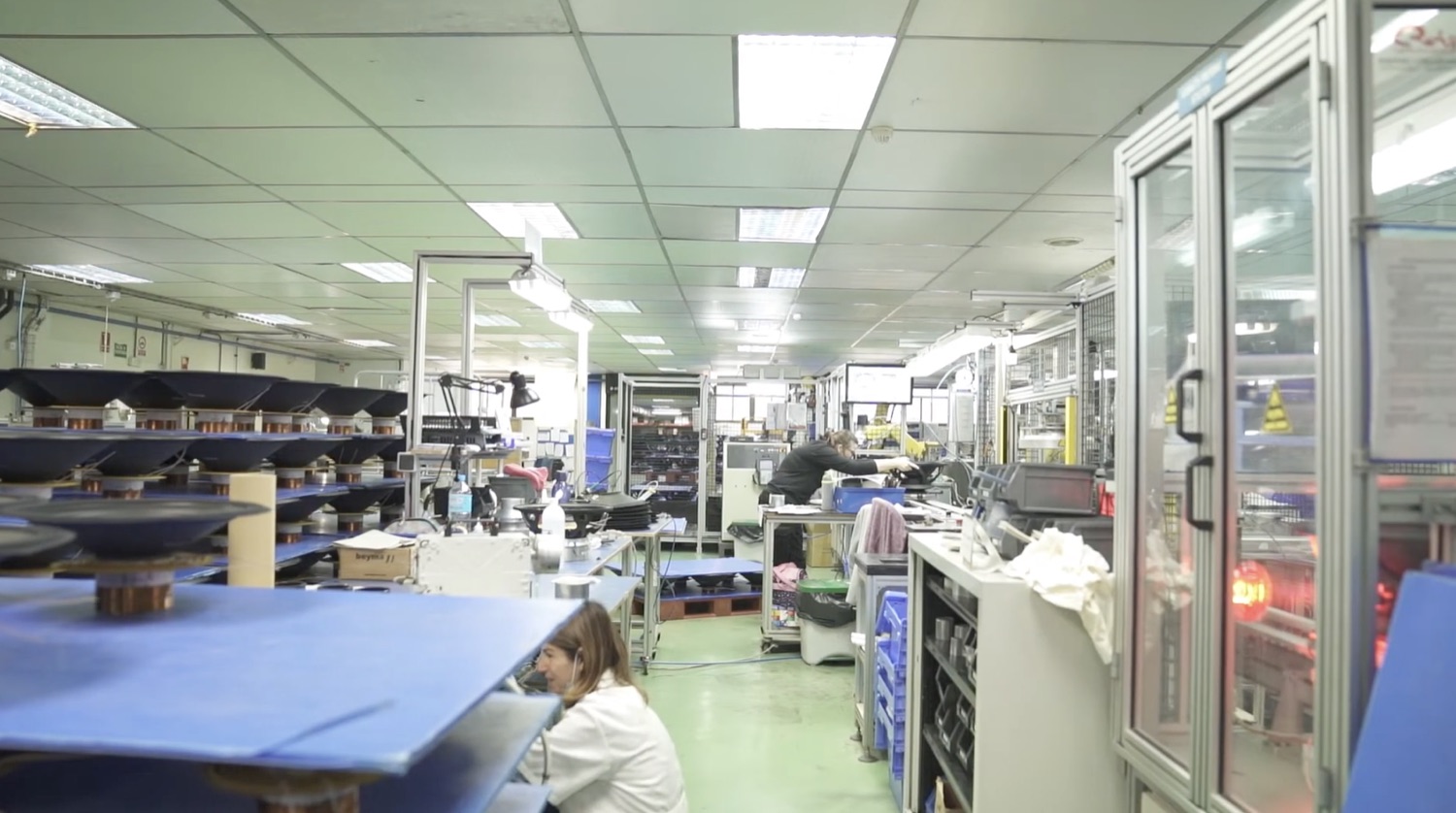
Beyma was founded in 1969, when the Masip family moved from Barcelona to Valencia to build loudspeakers. It designs and produces at its facilities in Moncada (Valencia). In 1974 it took its products to the Musikmesse fair in Frankfurt, and since 1976 it has exported across Europe; more than fifty years later it is one of the reference brands in professional audio.
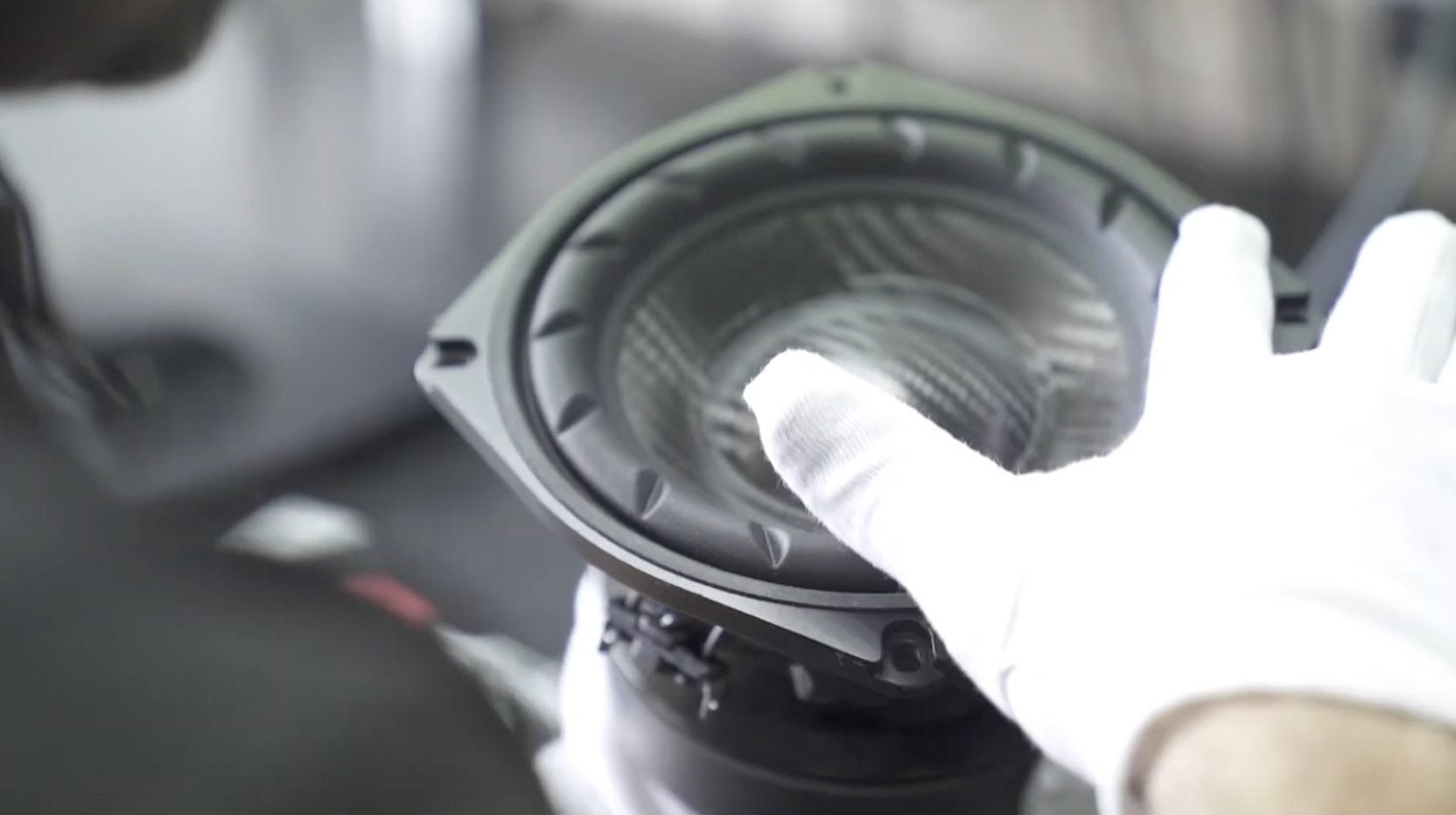
8″ woofer · low-mid
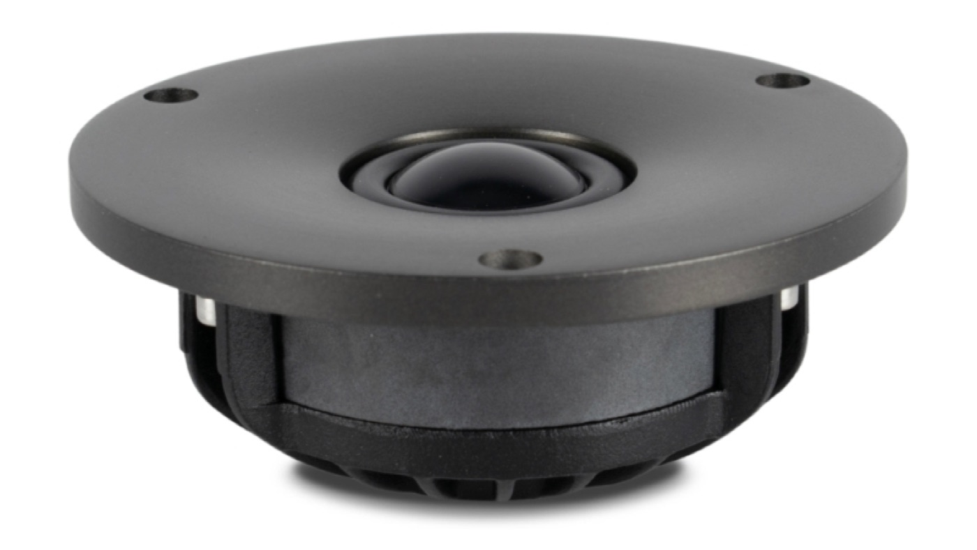
Dome tweeter · 1″
Measurements
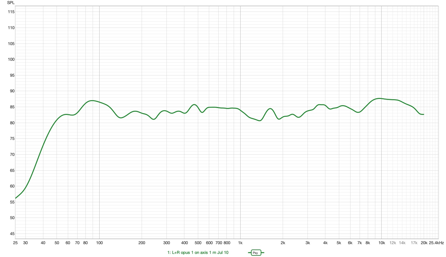
The plots below are preliminary: they were taken in an ordinary room —not an anechoic one— using time gating to isolate the direct sound. They are good enough to refine the design, but they are not the final word yet. Final certification will come with anechoic chamber measurements, and this data will be updated then.
A loudspeaker is not «tuned by ear». It is measured, corrected and measured again, dozens of times, until the numbers confirm what you are after. That is what separates real design from opinion, and it is how any project that means to reach the market is done.
A loudspeaker is, above all, a translator: it turns an electrical signal into sound. Ideally it invents nothing —it gives back every frequency, from the deepest bass to the finest treble, with the same weight it was recorded with. When we plot its frequency response (sound level against frequency), that fidelity shows up as a line as straight and horizontal as possible.
Every deviation from that line is a lie the loudspeaker adds to the music. A peak makes one area —bright treble, swollen bass— sound louder than it should and take over the rest; in time it tires the ear. A dip does the opposite: it buries information that was in the recording and that we will now never hear. A flat loudspeaker is not a «cold» loudspeaker, it is an honest one: the character should come from the recording, the room and your taste, not from a loudspeaker that colours everything the same way.
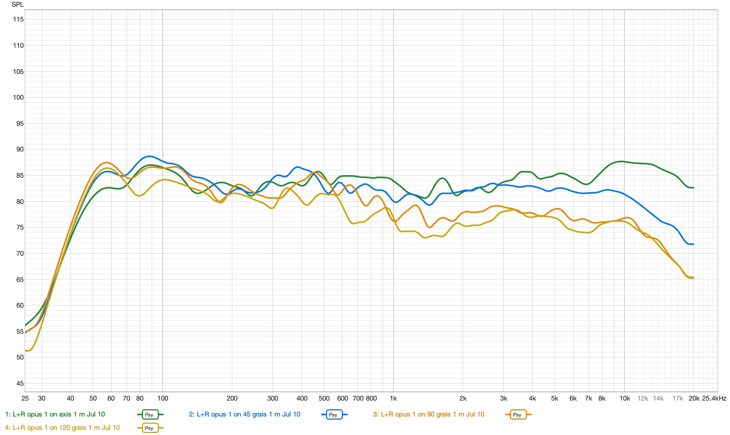
And it is not enough for the line to be flat right in front of the loudspeaker: what the sound does as it escapes to the sides and bounces around the room matters too (directivity). Toole and Olive showed that a flat on-axis response combined with directivity that falls off smoothly and progressively is, statistically, what listeners prefer in blind tests. That is the target behind every measurement.
Before spending a single euro on an anechoic chamber, the prototype is measured in an ordinary room. The problem is that walls, floor and ceiling send back echoes that dirty the measurement. The answer is not a perfect room but a rigorous method:
With this setup you enter the real working loop: measure, change one crossover value, measure again. Repeated dozens of times, this is what lets you tune the crossover until the target curve falls into place. The bass, where time gating stops being reliable, is measured separately in the near field and spliced onto the rest.
An anechoic chamber is a room built so that no echo exists: its walls absorb all the sound and the loudspeaker is measured as if it were floating in open space, with no reflections and no time-window limits. It is the perfect measurement.
But renting one costs thousands of euros per session. So it is not the tool you develop a loudspeaker with, it is the one that certifies it at the end: once the design has been refined with preliminary measurements, the chamber confirms the full response with total precision —including the bass region and the off-axis response— and seals the quality of the result. Taking a half-finished design into the chamber would be throwing money away; taking a polished one is the logical, responsible step.
Provisional data, measured in-room with time gating · pending validation in an anechoic chamber.
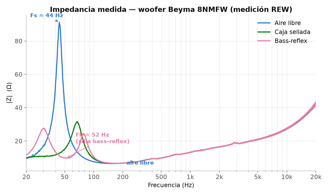
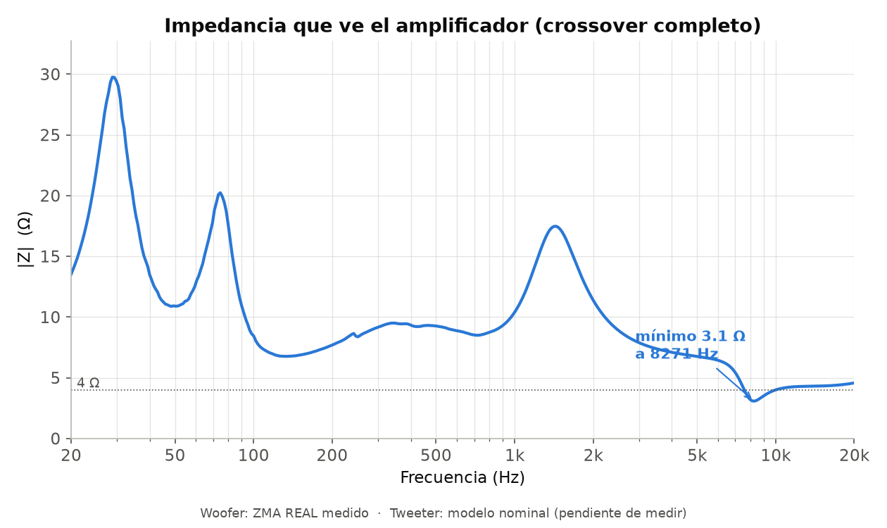
Impedance is the resistance the loudspeaker offers to the current the amplifier sends it, and it changes with frequency. Measuring it needs no anechoic chamber —an electrical setup with a reference resistor is enough— so, unlike the acoustic curves above, these are already final. And their shape is an honest X-ray of what happens inside the cabinet: where the woofer resonates, what frequency the port is tuned to, and what load the amplifier you connect will see.
Real electrical measurements. The system curve combines the measured woofer with a model of the tweeter, which is still to be measured.
Matching
It is the question that comes up most often and the one almost no manufacturer answers with numbers. Here they are: the Opus I is an easy loudspeaker to drive, and the measured impedance curve proves it.
Recommended power window
20 W120 W
per channel · amplifier stable into 4 Ω
The Opus I is rated at 4 Ω nominal, not 8: the 8NMFW woofer is 8 Ω, but the T25M tweeter is 4 Ω and the system minimum with the crossover fitted drops to 3.1 Ω around 8 kHz —a region where music carries very little energy. In the bass, where the amplifier is really asked for current, the load stays around 8 Ω. Any amplifier that claims stability into 4 Ω drives it comfortably, and today that is practically all of them.
With 90 dB sensitivity (1 W at 1 m), about 20 W per channel is enough to comfortably exceed 95 dB peaks at the listening position in a normal living room. Extra power is peace of mind, not a requirement.
High sensitivity combined with a load without extremes makes the Opus I a rewarding cabinet for valve amplification. A 20-30 W valve integrated has no trouble with it.
The terminal plate comes ready for bi-wiring or bi-amping if you want to explore that. It is not compulsory: with a single pair of cables the loudspeaker works exactly as designed.
Gallery
Real photographs of the build process in the workshop. No studio lighting and no retouching: the road from prototype to production.
Video
The build
Building the Opus I is not a carpentry exam. The design is worked out so the result depends on the project and not on the hands of whoever builds it: parts only fit in their correct position, the crossover arrives assembled and tested, and the steel rods themselves act as clamps while the glue dries.
The slices for both cabinets, numbered and already threaded onto their rods in assembly order.
Two 8″ Beyma 8NMFW woofers and two Beyma T25M tweeters, in their factory packaging.
Both crossover boards assembled and tested, the screws, the terminal plates and the sealing material.
The slices come in order, threaded onto the rods. You separate them, apply glue to the mating face and slide them back down the rods. Guided by the four steel axes, they cannot go out of square.
You tighten the nuts on the four M8 rods and the whole stack sits under constant pressure. That compression replaces clamps and guarantees the seal between layers, with no butt joints.
The crossover board is cut to the profile of the cabinet itself so it can go in through the woofer cutout, which is the only way inside. You place it and connect it to the rear terminal plate. Nothing to solder.
Woofer and tweeter are screwed into their baffle rebates, which leave them flush with the wood. You connect the spade terminals, watching polarity, and close it up.
The cabinet arrives in bare MDF, ready to paint, lacquer or treat. This part is yours: it is where the kit stops being a product and becomes yours.
Open source
We believe in shared knowledge. With the launch of the kit, the cutting plans, the 3D models and the crossover schematic will be released free of charge. The links in grey are not available yet.
Cutting files for the 23 slices and the baffle of the «Lira» cabinet.
Custom rear terminal plate in laser-cut black acrylic: engraving and holes for the binding posts.
Jantzen Audio passive crossover.
Official Beyma datasheets for the drivers in the kit.
How to get one
The Opus I comes in two forms, so you can pick the one that suits you: build it yourself and save while getting to know the loudspeaker from the inside, or receive it finished and ready to play.
Coming soon First series reservation
Limited, numbered series
Reservations for the first Opus I series open soon: numbered, hand-signed units, paid in instalments and refundable until dispatch. Leave us your contact details and we will let you know as soon as it opens.
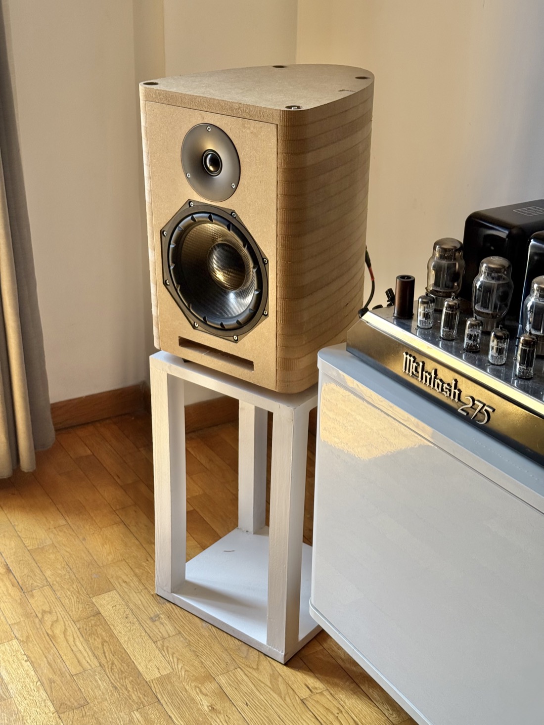
Option 1 · Kit
You get the Opus I in three boxes and assemble it yourself, guided step by step.
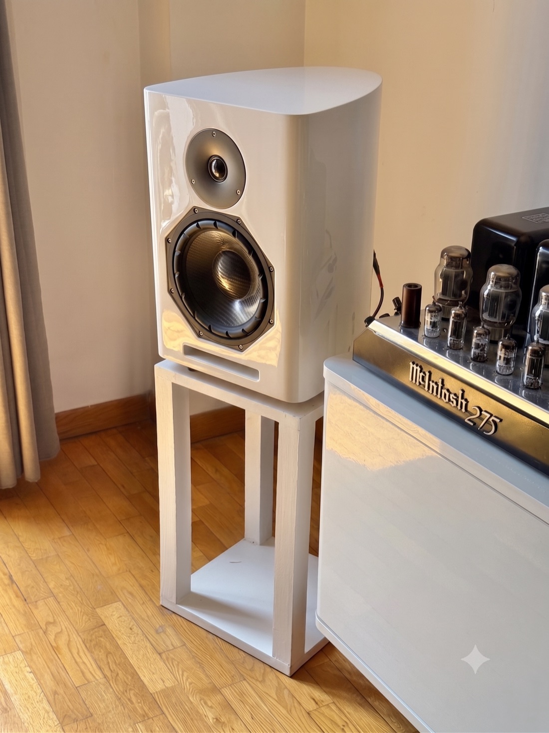
Option 2 · Assembled
You receive the cabinets finished in the workshop, ready to place and connect.
These images are simulations, not real samples. The final finishes are still to be decided.
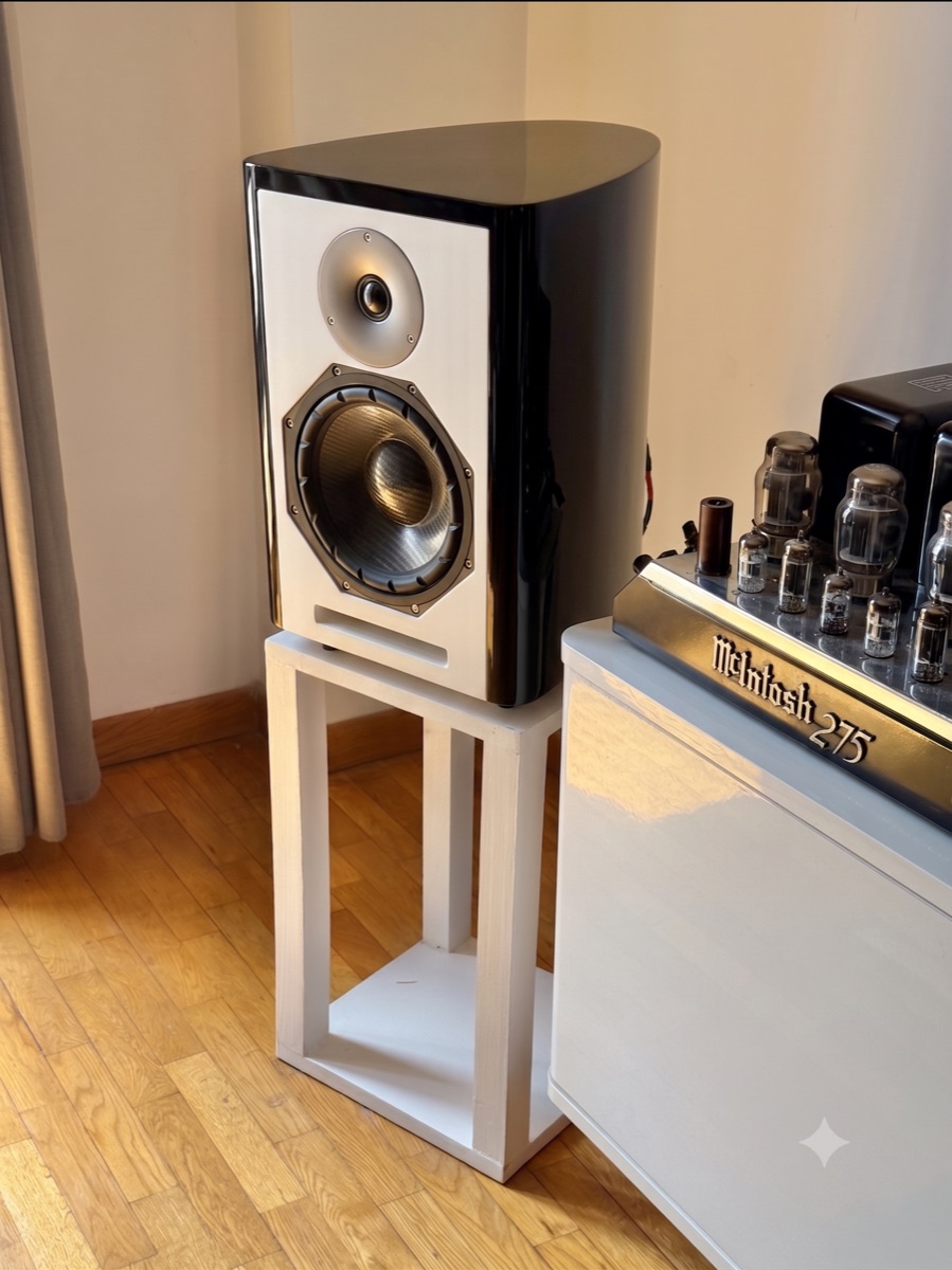
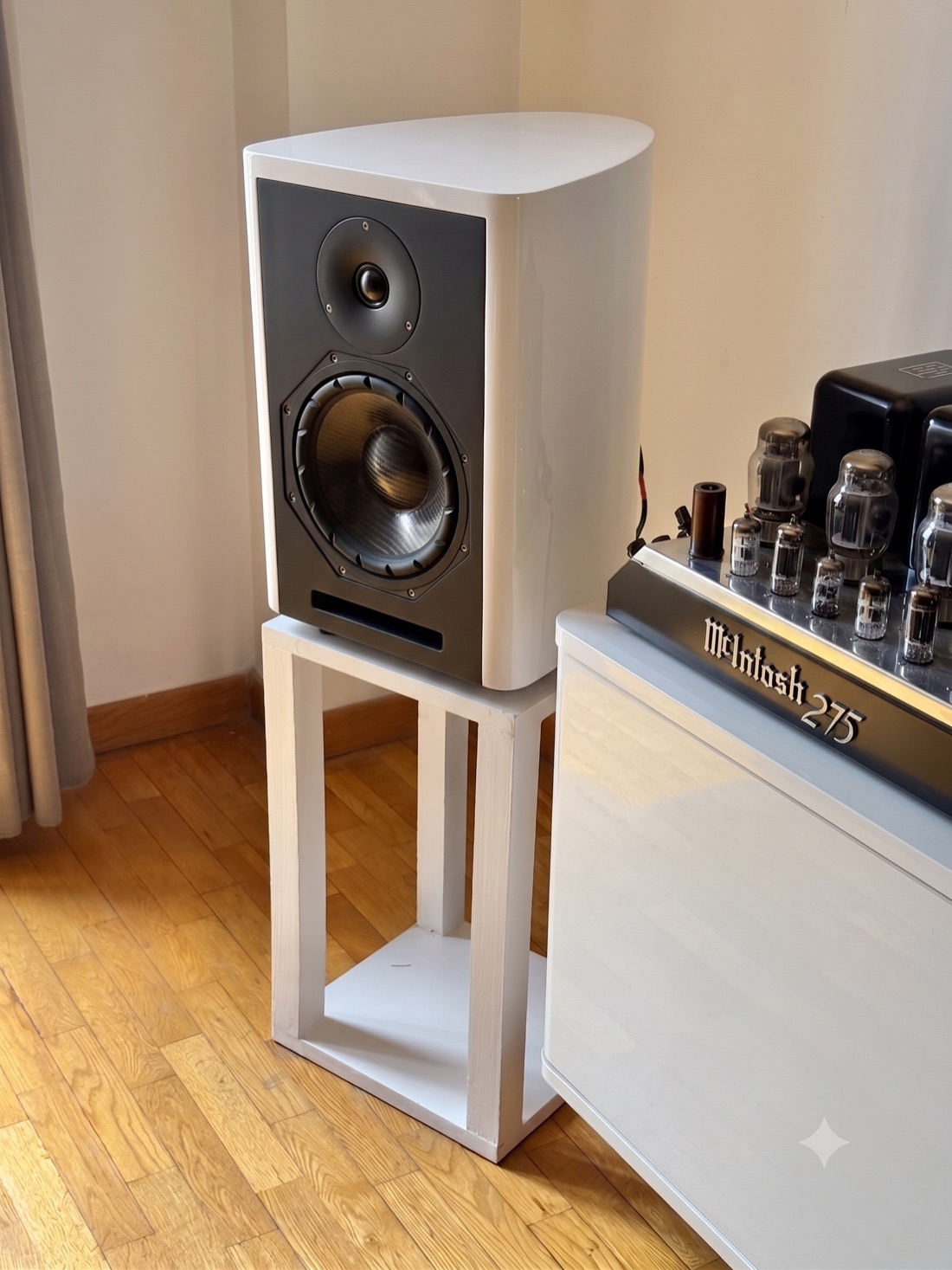
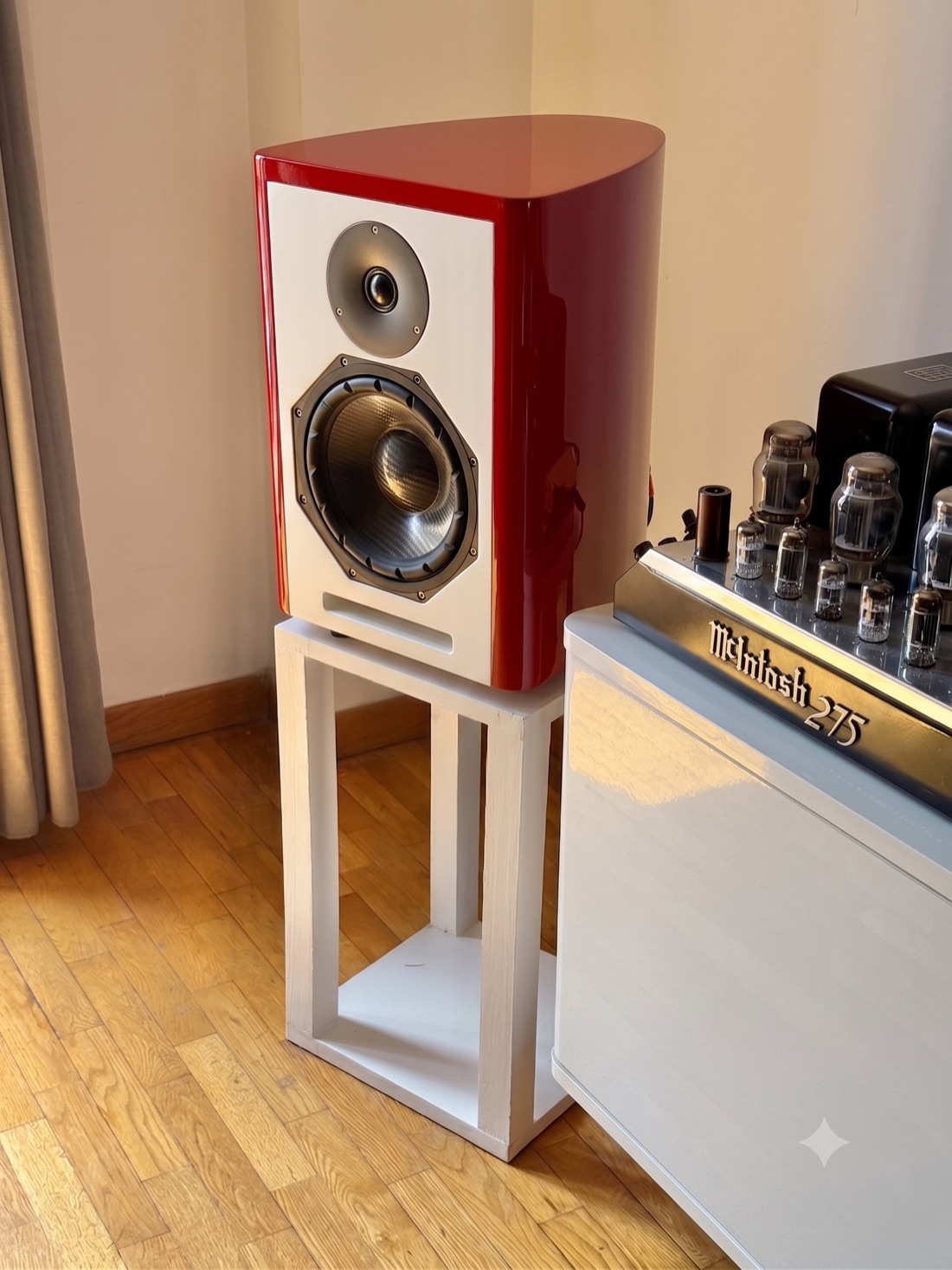
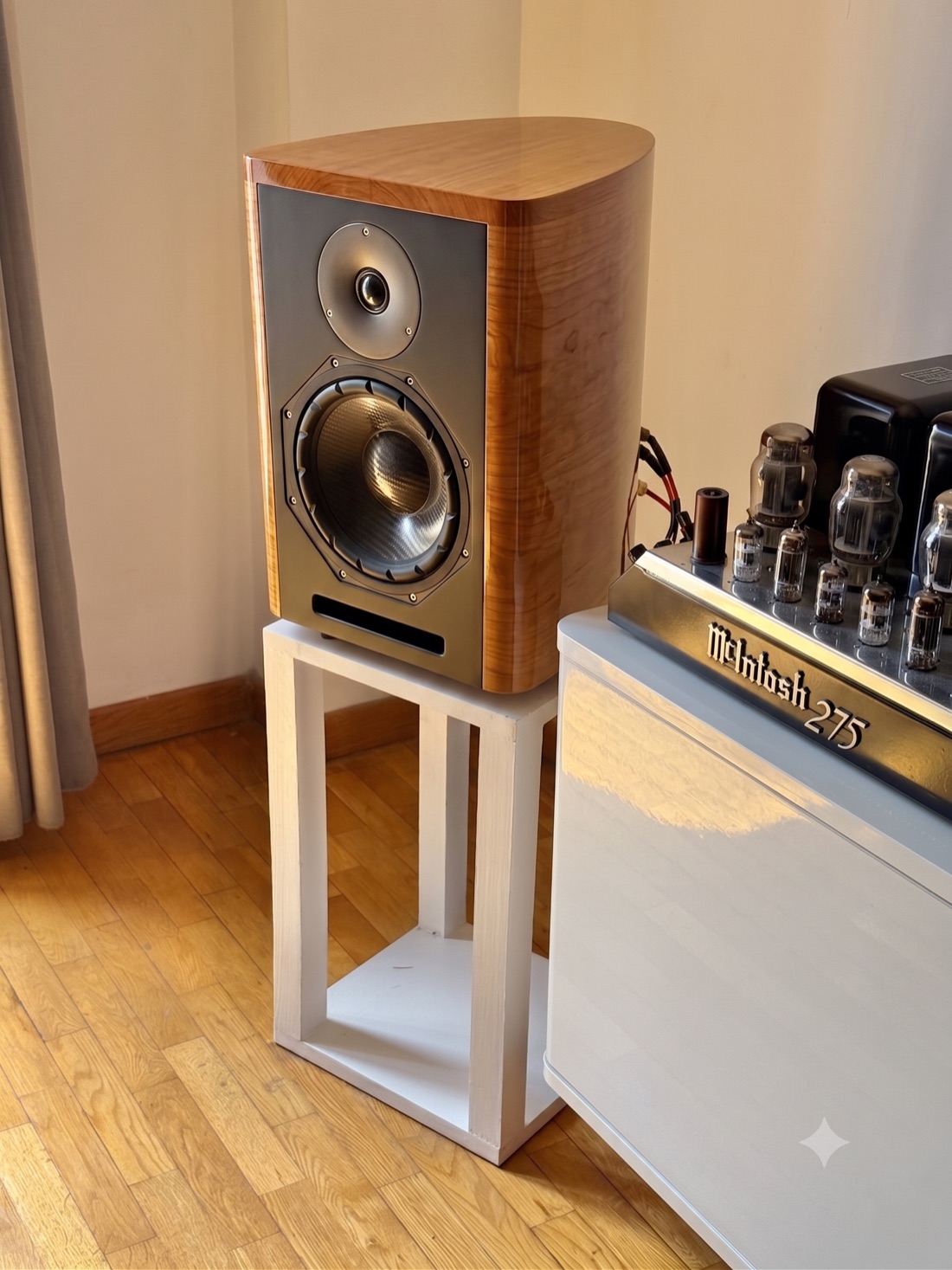
If you already own part of the system or prefer to spread the cost, it is also available module by module. The drivers are offered at retail price; the saving is in building the cabinet yourself, avoiding manufacturing, packaging and shipping costs.
Questions
That the design is final —the «Lira» cabinet, the Beyma drivers and the Jantzen crossover you see in the specs are the ones being manufactured— but the product is still in its last stage of refinement: the finish is being settled and the anechoic chamber measurements are still to come. You can follow the real state of the project on the timeline at the top of this page, which is updated as things move.
No. The finish images are simulations, not real samples, and the final finishes are still to be decided. The finish depends on how you buy the Opus I:
That is the reasonable worry of anyone considering a kit, and the design is built around it: the slices are numbered, threaded onto their rods and tongue-and-grooved, so they only fit one way. The crossover arrives assembled and tested, so there is nothing to solder and nothing to calculate. While the glue has not set you can still correct the position of a slice. And if you get stuck, you write straight to the designer: there is no customer service department in between.
No. The build takes about two hours for the full pair and needs no soldering, no clamps and no special tools: the four steel rods do the clamping while the glue dries. The «The build» section on this page has the detail on level, time, tools and what is in each box.
The Opus I is designed in Barcelona and the drivers are from Beyma, who design and manufacture in Moncada (Valencia). The CNC machining of the cabinet and the lacquering are also done in workshops around Barcelona. To date it is the first commercial loudspeaker kit designed and manufactured in Spain with Beyma drivers.
Yes, the 3-year legal warranty. And since it is hand-made by its author, anything that comes up is dealt with directly, with no middlemen.
Public presentation
Autumn 2026
If you want to hear about the first listening sessions or the details of the limited series pre-order, leave me your contact details.
Log in for more features

Community
Questions and answers
The channel is open to discuss simulations, suggest changes or sort out technical questions directly with the designer.
Join the Opus I community
Come into the project group to follow the build, share your own progress and sort out technical questions directly with the designer.
0 comments
Sign in to ask or comment.
Sign inLoading…